Use Your Browser's [Back] function to return to where you were.
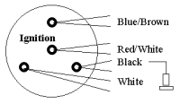
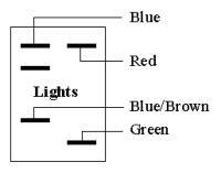
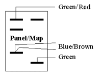
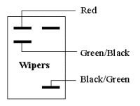
These are diagrams I made while disassembling the Tomato's electrical system. They are drawn from my perspective before anything was disconnected, and some wire connections have been altered for layout. Schematics are fine, but for dummy-friendly reassembly an actual map of connections is better. In these diagrams multiple colours are specified as Stripe/Base (e.g., R/W), unlike other diagrams that (might) use BaseStripe (e.g., WR).
THERE WERE ERRORS AND HACKS IN THE HARNESS, REFLECTED IN THESE DRAWINGS.
See Devices: As Designed for diagrams that match the Electrical Schematics.
| Engine Bay |
| Fuse Box |
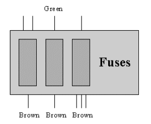 | |
| Voltage Regulator |
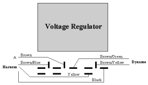 | |
| Starter Solenoid |
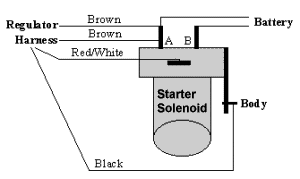 | |
| Coil |
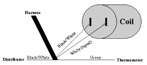 | |
| Gauges |
| Fuel |
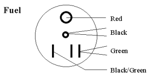 | |
| Water |
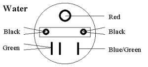 | |
| Speedometer |
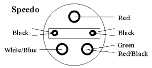 | |
| Tachometer |
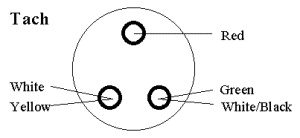 | |
| Switches |
| Ignition |
 | |
| High Beam |
 | |
| Lights |
 | |
| Panel/Map |
 | |
| Wipers |
 | |


